

A customer of ours recently wrote a great blog post about how he exports XY data from Eagle. He was new to the process and upon investigating found that it wasn't as easy as you might expect. Go check out his post here if you'd like to find an easy way to do this yourself.
Mention in The Boston Globe

We got a nice mention on the front page of the Sunday edition of The Boston Globe this weekend. The piece, written by Jon Christian, was all about our New England Factory Tours group that we organize on Meetup. We'll be hosting another group tour here shortly. Check out the tours page to see upcoming events.
PCB Design - Minimum Silkscreen Parameters

Example of silkscreen that is too small
Just a quick note today about silkscreen and how to make a success of it. Bigger silkscreen is easier to manufacture so if you can get away with larger characters and wider lines, go for it. The team here will appreciate you saving their vision too (microscopes are expensive).
But if you have a small product and still want silkscreen there are some parameters you might find useful. There are two ways to put silkscreen onto a PCB. A conventional squeegee and screen, or the more expensive automated computer controlled inkjet printer.
Squeegee and Screen: Font Size 30 mil x 30 mil, with a 6 mil draw (line width)
Inkjet Printer: Font Size 20 mil x 30 mil, with a 5 mil draw (line width)
Remember, these are minimums, so you're still pushing the process. If you design a little larger then your silkscreen will fit comfortably within the process window.
I hope you find that useful. As always, if you have any questions, please feel free to get in touch. My email address is cdenney@worthingtonassembly.com and our phone number is (413) 397-8260.
We Have A New Website
It had recently come to our attention that our website was a bit... long in the tooth. So we spent some time over the holiday break to update our website.
The short story is, we have a fresh new look and the layout is much simpler and should load much faster.
The long story is that we were formerly hosted on HostGator and used Wordpress as our content management system. This worked ok, and was SUPER cheap, but there's so much management with Wordpress. We would get so much spam that we had to turn off our commenting system. Plus, in order to get things to render properly in all browsers we had to constantly edit the code that displays the page. The worst part is that whenever we had to perform an update to the theme (which was quite often) we'd have to re-edit the code every time. Eventually, we just got tired of dealing with it and let it languish. And something as important as a website should not be neglected.
I've been hearing ads for Squarespace for years. They even had a commercial for the 2014 Super Bowl. I had avoided trying it because I didn't want to learn something new. But after playing with it for just 30 minutes, I felt like an expert. The software is really impressive and the mobile app for putting together blog posts is really slick. So we decided to switch over to Squarespace for hosting our website and we're pleased with the results. If you haven't checked it out head on over to www.worthingtonassembly.com and take a look.
For those of you who subscribed to the blog via email, nothing should change except the delivery system of the email. You'll be getting the emails from MailChimp now and the format should look a little different. For those of you that subscribed via RSS, you will need to update your RSS URL. I'm just not technically astute enough to know how to automatically do this. And if you're reading this, you're presumably interested enough to want to resubscribe manually. The new URL is http://www.worthingtonassembly.com/blog/?format=rss
Thank you all for reading this blog and if you ever have any questions, please don't hesitate to get in touch.
Octopart's Common Parts Library
Today Octopart announced what I think is a really valuable tool. The Common Parts Library We worked with Sam and Janine over at Octopart and helped them identify popular, and more importantly, readily available parts to build a common parts library. This will be a library of components that are known to be well stocked at distributors and perhaps even your contract manufacturer (like us). What will make this library particularly valuable is when you're designing a new product and you just need to find a basic resistor, cap, LED, oscillator, or some other such part to perform a simple task, without diving into the complicated filter engines of large distributors.
Just browsing the library makes me want to design a new board. I hope you find it valuable and let us know if you think anything is missing.
Tessel Manufacturing
Here's a video we put together to show the Tessel being manufactured at our site in South Deerfield, MA. http://youtu.be/KiD3BK56GrI
Cloud Based Circuit Board Assembly
We are so excited to finally be able to announce that WAi and CircuitHub have partnered together to change the way circuit boards get assembled.

The short version is, you can head over to CircuitHub.com and have your BOM, PCB, and Assembly quoted instantly via CircuitHub's app. CircuitHub handles all of the ordering and logistics for you and boards just arrive at your door. But it goes much much deeper than that.
Here's the long version...
The path to this type of service is littered with the remains of countless hours and effort to make buying assembled PCB's easier. Assembly is expensive, there's a lot of duplicated effort, and you really need to have experience with the whole process in order to get what you expect. Finding trusted partners (like WAi) is not easy. So for years people have been trying to make it easier and less expensive.
CircuitHub's idea is simple. Use your own EDA tool, upload your files, and choose specific manufacturers for each of your parts. From there they take advantage of the community they're building to standardize their component library and buy in bulk, then pass the savings onto their customers.
Let's take an example of a typical circuit board we see here. Your BOM for a single piece is about $20. Now you need to buy circuit boards. Well you only need 10 so that'll probably run you about $300. Then you need to get them assembled. Your assembly house has a ton of work they need to do in order to prepare to build your assembly. So you're looking at about $500 for the assembly plus a $300 stencil. So to get just 10 boards assembled, you're going to be out $1,300.
One of the advantages that large companies have over small companies is that they can support their own in house manufacturing and not rely on contract manufacturers like ourselves. When you have a dedicated engineering team, they can stick to a standard component library and then the business can buy those components in large quantities and save a lot of money. In contract manufacturing, you need to buy very small quantities because every engineer is using a different part. So we need to purchase exactly the right part for you that you specified. Using CircuitHub's "Part Rank" the community decides which parts should be used. When all of the designers are using the same 10K resistor or Atmel chip, we can buy 10,000 of them instead of just 6 for your project alone. To give you an idea of the cost savings we're talking about, for a run of the mill MCU like the ATMEGA32U4-AUR we would have to buy each chip at about $7.00. If we could buy 10,000 because everybody is using them, then we could pay about $3.50. That's half. Now multiply that kind of cost savings across your entire BOM. Now you're getting an idea of just how much money we can save here.
So now we've reduced the cost of your BOM from $20 to $10. Over 10 boards, that's a $100 savings.
Now to buy your boards. Well you're just a small guy. You don't buy a whole lot so the board house is going to have to put in extra effort to manage your build. So you're going to pay a premium rate. But with CircuitHub, since they're buying for the whole community, they'll have purchasing power and leverage that the little guy can only dream of.
Assembly is where a huge cost comes in. Stencils are expensive, programming the machines, setting up the feeders, profiling your assembly for the reflow oven, I could go on. This is where CircuitHub truly shines.
They've fully integrated their software into our systems. They have the ability to read our inventory levels, set up automated purchasing, automatically push programs directly into our pick and place machines, auto generate purchase orders and define production sequences. All of these things today are done manually, by a person sitting at their desk and parsing the information supplied to them to figure out what is required to assemble your circuit board. These tools should significantly reduce costs and we fully expect that CircuitHub will be able to beat our own internal pricing on most orders because of these efficiencies.
Not only that, but when the community settles around a fixed number of components, these components can have feeders dedicated to them. So we only have to plug the feeder into the machine and say "Go!" For small prototype runs of about 10 pieces, easily 25% of the cost is simply loading feeders with the components needed for each job.
Yield can be improved as well. We've seen easily over 20 different footprints for an 0603 resistor. That is crazy. Each footprint has its own characteristics in the reflow oven and not all of them work well. It's not uncommon to get a great deal of "tombstone" or "head-in-pillow" defects from a poor footprint. But if you use CircuitHub's footprint, then you know that we've seen it before and we can guarantee a high yield with that footprint.
I cannot tell you how excited we are to be a part of this and I can't wait for this awesome community of engineers and developers to start making cool products that we can all enjoy at an affordable price.
- Chris Denney, CTO
Video: The Machine to Build the Machines
Fascinating video of how the original NeXT Cube's circuit board was made. It's actually a fairly good explanation of how SMT manufacturing is still done today. It is a little different (and much faster) but all the basics are there. What's so interesting to me is how far ahead of their time these manufacturing engineers were. They had 3-dimensional solder paste inspection in the 80's. That's amazing. 3D SPI has mostly been considered a modern technology. The NeXT engineers were truly ahead of their time. I would love to talk to whomever was responsible for this assembly line someday.
Selective Soldering Tips: Using the Machine for Rework
 Ok, I confess. Sometimes we do make mistakes. As much as I hate to admit it, it does happen. For example, we've seen headers not fully seated to the board. They're a little bit crooked or one edge is touching the PCB, while the other edge is so far up in the air that you can't even see the pin protruding through the other side of the board. Other times, you have an edge connector that needs to protrude through a cover panel and there's no room for play. The connector must be perfectly flat and perfectly square. If you find yourself in this situation, your selective soldering machine can be your best friend.
Warning! On some machines, you may be required to bypass security features. Please consult your manufacturer before bypassing anything designed to protect you from a dangerous machine.
Ok, I confess. Sometimes we do make mistakes. As much as I hate to admit it, it does happen. For example, we've seen headers not fully seated to the board. They're a little bit crooked or one edge is touching the PCB, while the other edge is so far up in the air that you can't even see the pin protruding through the other side of the board. Other times, you have an edge connector that needs to protrude through a cover panel and there's no room for play. The connector must be perfectly flat and perfectly square. If you find yourself in this situation, your selective soldering machine can be your best friend.
Warning! On some machines, you may be required to bypass security features. Please consult your manufacturer before bypassing anything designed to protect you from a dangerous machine.
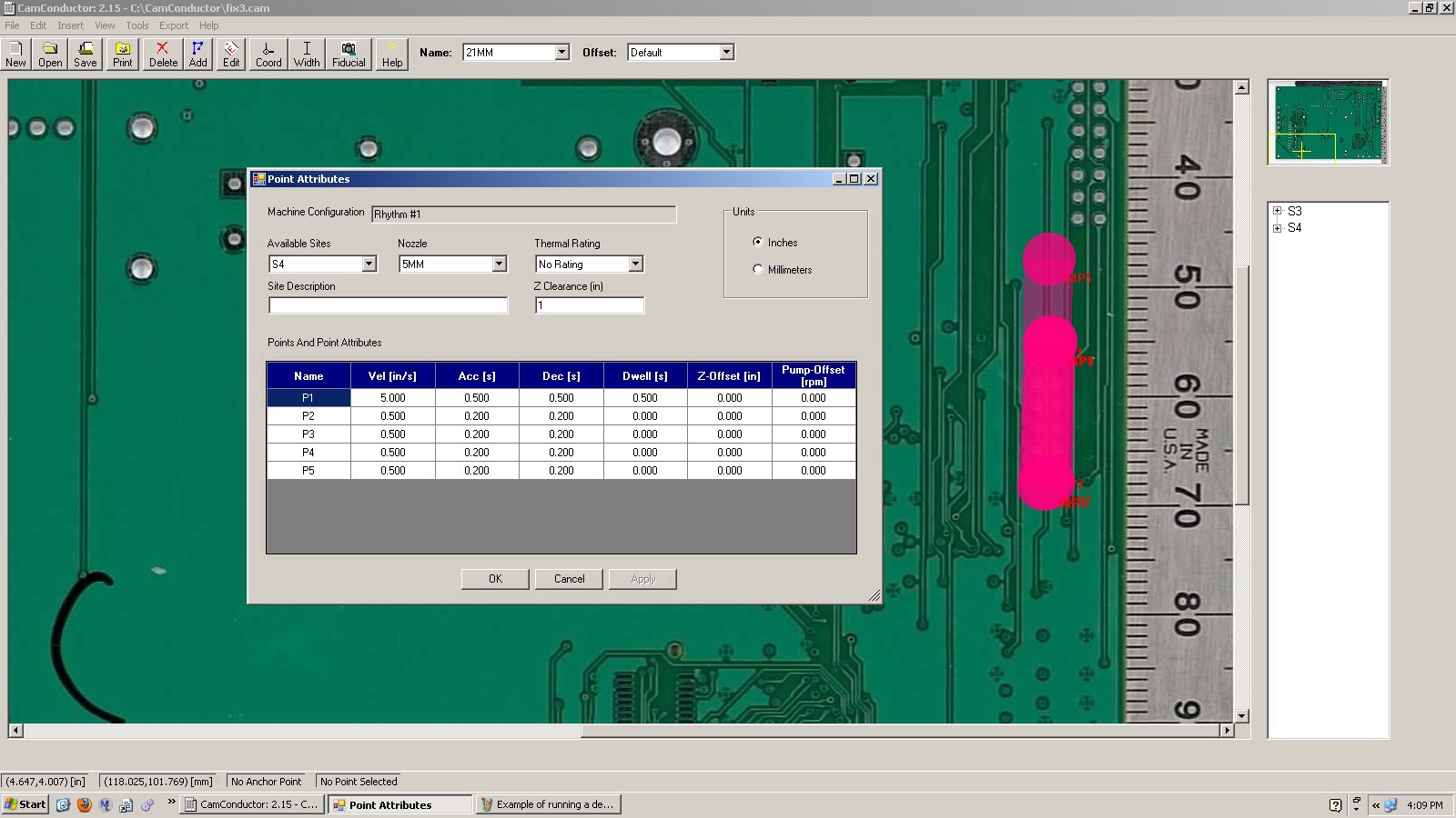
If your connector is larger than the size of your nozzle, you'll need to program the machine to "walk" back and forth over the pins of the connector, as seen in the image above. There's a limit to how long of a connector you could reasonably rework using this method. But we've been able to fix 2" long connectors on 4 layer boards. The key was to make sure the nozzle could dwell a little bit on the pins that were connected to ground.
Every connector is different. Some connectors will become damaged with its much exposure to heat. The plastics just are not designed to handle it. For these connectors, we find it's best to just remove the entire connector and insert a brand new one. Other connectors however hold up well under the heat and you'll be able to apply slight pressure with your hand to push them back through the board. Be careful however, as a lot of times pushing the pins down will also push the solder down, and you'll have no top side filet.
Make sure to preheat the board. You don't want to hit this cold board with a bunch of molten solder. The thermal shock could shorten the lifetime of the assembly. So make sure it's nice and hot before you begin.
Link: The Hardware Revolution Is Upon Us And Why It Matters
Link: The Hardware Revolution Is Upon Us And Why It Matters Excellent article from venture capitalist firm True Ventures. We're seeing more and more investment in small businesses that are trying out new hardware ideas. Finally the venture capitalist world is waking up to this. There's so much I could say about this but True Ventures has already said it so well.
Selective Soldering Tips: Touching Surface Mount Components
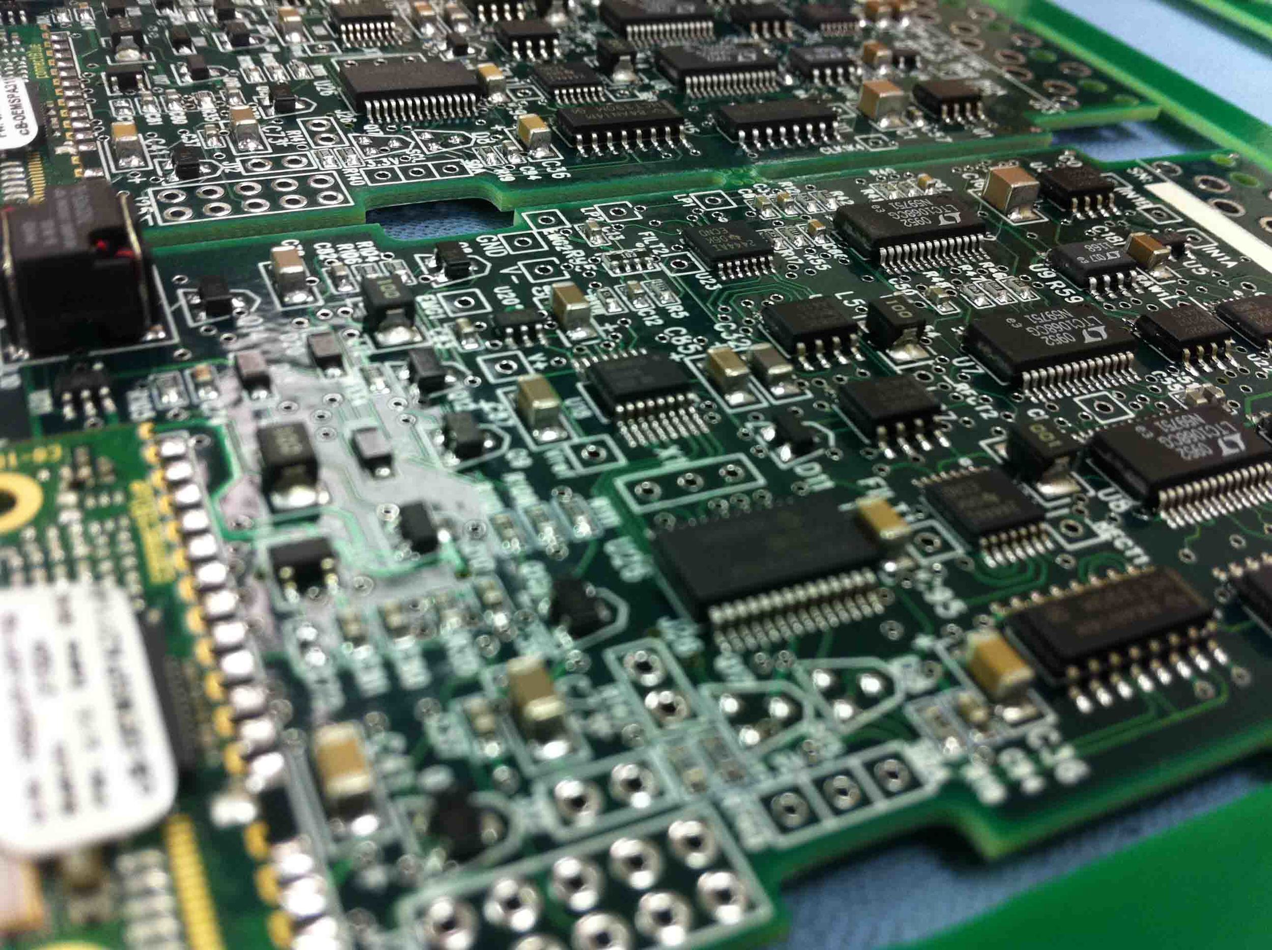
This is just one article in a series of articles discussing tips and tricks for using a selective soldering machine. Here at Worthington Assembly Inc. we have a selective soldering machine manufactured by RPS Automation. Our particular model is a 2010 Rhythm model. These article are written by the same person who's used this machine every day for years. One of the beautiful things about selective soldering machines (vs. wave soldering machines) is that you can easily route around surface mount components that are mounted on the bottom side of the board. But it's not always that easy. For example, what happens when the board designer ran out of room and had to put surface mount components right next to the thru-hole components?
Well, believe it or not, you can actually safely make contact with surface mount components, so long as you reflow only one side of the component at a time. This requires that the design of the board has the surface mount components perpendicular to the plated thru-holes.
As you can see in the image above, the path of the nozzle crosses right over 9 surface mount components. The area where the nozzle makes contact with the component will reflow the solder that was deposited from solder paste, but the opposite side of the component will remain solid and hold the component in place. This can definitely make you a little nervous the first time you try it, but I assure you that component will stay put.
It would be a good idea to let your board designers know about this. Many designers would like to use every square centimeter of their board, and letting them know that they can put surface mount components very close to their plated thru-holes, so long as they are perpendicular to the holes, will certainly make them happy.
As always, if you have any questions, feel free to give me a call at (413) 624-6879 or send me an email at cdenney@worthingtonassembly.com.
WAi - Best Practices
I'd like to announce that we've added a new section to our website called "Best Practices".
Over the years, customers have asked us how they can best design their boards so that they're as simple for WAi to build as possible. A lot of the questions revolve around how our automated systems handle the circuit boards during the assembly process. So the first document we put together is called "WAi Board Design - Best Practices for Automated Handling" which can be found here.
We'll try to update this page whenever we find customers asking us the same questions regularly. If you have a question about how best to design your board, please get in touch. We're happy to help.
The Top 10 Myths About Selecting a Contract Manufacturing Partner
Ron Keith (CEO) of Riverwood Solutions wrote a nice article for Industry Week discussing myths about selecting a contract manufacturing partner.
I generally don't care for "top ten" lists, but I understand their appeal. Regardless, Ron seems to have his wits about him and makes many sound points. I particularly appreciated this sentence.
Effectively working with contract manufacturing is a fairly complex business relationship that must function well across a number of functional areas.
Link: How to Do On-Shoring Right
How to Do On-Shoring Right Great article discussing Avigilon's domestic manufacturing. Interesting that they're manufacturing in Canada when they're a US company, but I'm sure they have their reasons. Either way, it's obvious that manufacturing in North America can be done effectively and cheaply.
Design for Manufacturability (DFM): Use Surface Mount Components (SMT) - Part 3 of Many
This is just one article in a series of articles discussing design for manufacturability for electronic assemblies. As a contract manufacturer we see every possible design decision you can imagine. We know what works, and we know what doesn't. We're happy to look at your assembly for any manufacturability concerns, whether we're building the assembly or not. Remember, rule number 1 of DFM for electronic assemblies
"Whenever possible, use surface mount components instead of thru-hole components."
In my first article discussing the importance of using SMT components instead of thru-hole components I mentioned that there are exceptions. The most obvious and important exception is any component that is going to experience a lot of external force. Generally, these are any type of connector where the user will be plugging and unplugging cables often. The amount of force that these connectors experience can be pretty light. But what happens is, overtime, all of those forces stack up and cause the solder joints to weaken. Eventually, those solder joints, or the copper pads that they're connected to, will fracture and you will be left with a broken product.
But connector designers have become wise to this. A lot of modern SMT connectors are coming with tooling pins that are inserted into the board, without solder, or massive leads that are soldered to equally massive copper pads, that can help direct some of the brunt of the force away from the fragile solder joints and copper pads.
IMG_0949 - Version 2
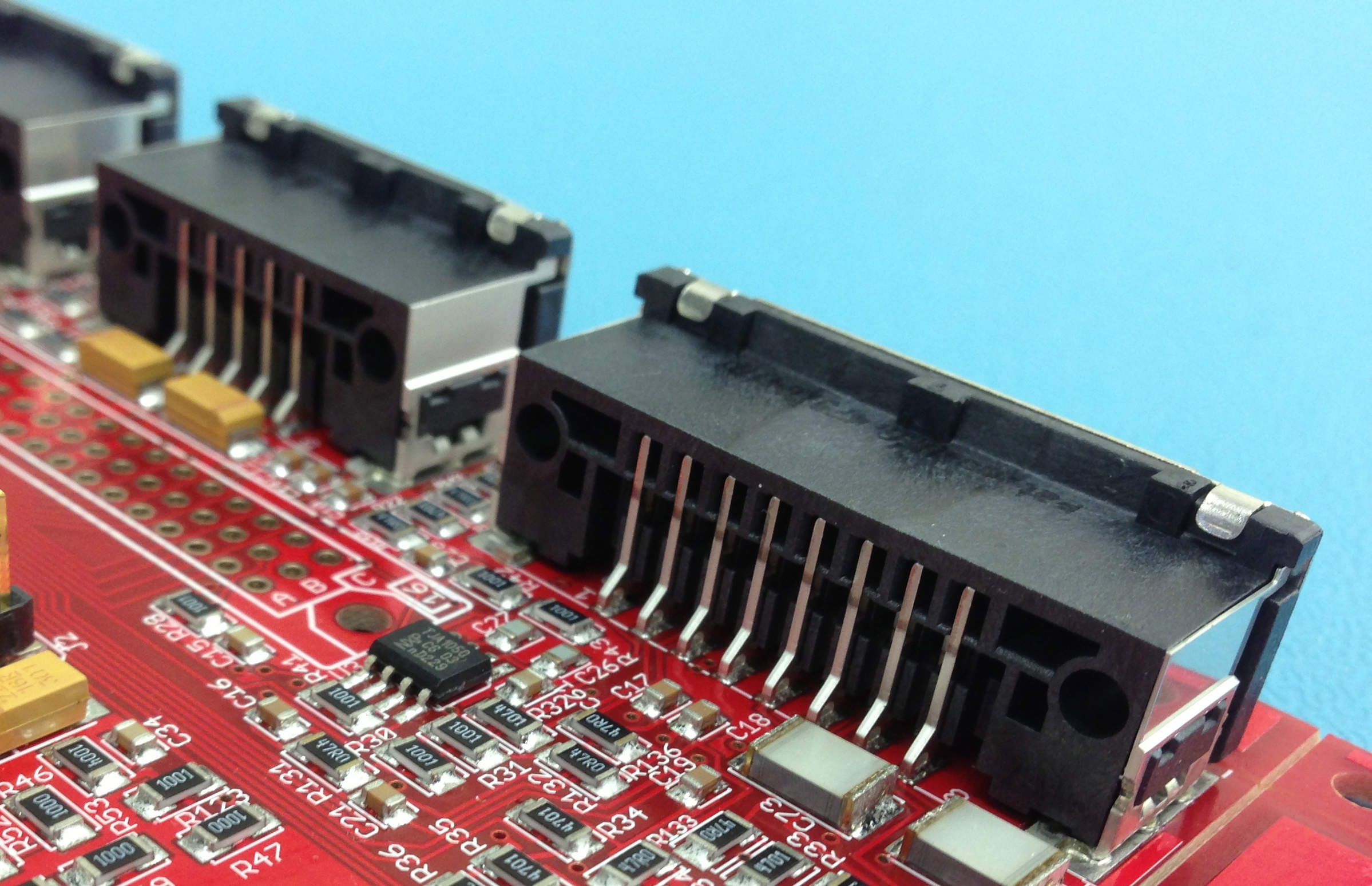
As you can see in this picture, there are is a huge contact area on the edges of these D-Sub connectors. These connectors are rated for over 400 cycles. It is very rare for any connector to see that many cycles (except for cell phone connectors which may see as many as 1,000 cycles in its lifetime and they still use SMT connectors). This component was placed automatically with a machine and soldered the same way as all of the other surface mount components on this board. This takes far less time for us than any thru-hole equivalent, and ultimately saved our customer a lot of money.
So, even when it seems like a thru-hole component is absolutely necessary, please consider the alternative. It may save you a lot of money too.
As always, if you have any questions, feel free to send me an email at cdenney@worthingtonassembly.com or follow me on Twitter @WAssembly.
Design for Manufacturability (DFM): Use Surface Mount Components (SMT) - Part 2 of Many
This is just one article in a series of articles discussing design for manufacturability for electronic assemblies. As a contract manufacturer we see every possible design decision you can imagine. We know what works, and we know what doesn't. We're happy to look at your assembly for any manufacturability concerns, whether we're building the assembly or not. Remember, rule number 1 of DFM for electronic assemblies
"Whenever possible, use surface mount components instead of thru-hole components."
The number one reason we tend to hear here at Worthington Assembly, about why designers don't want to design their boards with SMT components is that if the designer needs to remove components himself then SMT components are too difficult to work with. This also happens to be the worst reason in my opinion for choosing thru-hole components. SMT components are actually far easier to work on with just a soldering iron than thru-hole components. When a thru-hole component is well soldered, you're going to have a really hard time remove it with just a soldering iron. You have to heat up one leg, grab it with a pair of pliers, pull the lead through the hole, and pray that you don't damage the barrel while doing it. Then you need to do the same to the other side. SMT components however, are quite simple to remove with a soldering iron. We call it the old "blob of solder" removal method. Take your soldering iron, take your solder wire, blob a whole bunch of it on the tip of the iron, set that blob onto of your SMT resistor and then just lift up. The surface tension from the solder will cause the SMT resistor to come right up with the tip of the soldering iron. It could not be any easier.

IMG_0959

Now, there's another reason designers may choose thru-hole components instead of SMT components that is related to what we just discussed. This is the thought that it's easier to assemble a thru-hole board by hand than it is to assemble an SMT board by hand. This can be true. Sometimes it is easier to procure material and handle that material than it is to handle the same SMT material. If you're building just one board, and only one board forever, then this is probably ok. DFM shouldn't even be considered in that case. But if you expect to sell even a few dozen pieces of your design (or millions!) then you will definitely want to start with an SMT design from the beginning. And I think you will be surprised. With the right tools, like a tweezer soldering iron, SMT components can be soldered really easily.
As always, if you have any questions, feel free to send me an email at cdenney@worthingtonassembly.com or follow me on Twitter @WAssembly.
Design for Manufacturability (DFM): Use Surface Mount Components (SMT) - Part 1 of Many
This is just one article in a series of articles discussing design for manufacturability for electronic assemblies. As a contract manufacturer we see every possible design decision you can imagine. We know what works, and we know what doesn't. We're happy to look at your assembly for any manufacturability concerns, whether we're building the assembly or not. Surface Mount Technology (SMT). The single greatest thing to happen to the manufacturability of electronics since the printed circuit board itself. Rule number 1 of DFM for electronic assemblies
"Whenever possible, use surface mount components instead of thru-hole components."
There are exceptions of course, but generally speaking surface mount components are almost always easier to assemble than thru-hole components. Primarily, this is because of the equipment that most electronics manufacturers employ. Even if your contract manufacturer has fully automated thru-hole equipment, it's likely still easier for them to assemble your design using surface mount components than it is thru-hole components. Today, the fastest SMT machines can pick and place components as fast as 120,000 times per hour. The fastest thru-hole machines still pale in comparison at 26,000 components per hour, and thats only for axial components. Radials are even slower to assemble at 22,000 components per hour.
Surface Mount Example
Remember, time is money when it comes to assembly work. Your manufacturer is charging you for their time. So if he can assemble your board at 120,000 CPH instead of 22,000 CPH, he's going to be able to deliver your product sooner and you'll be saving money.
But placing/inserting the components is only half the battle. You still need to solder it. With surface mount components, all of the soldering is done automatically using solder paste and a reflow oven. Thru-hole components need to either be wave soldered (if designed properly), selectively soldered (if designed poorly), or *gasp* hand soldered (when you really just didn't even think about manufacturability). Talk about taking a long time. Thru-hole soldering is not as easy as it might seem. Yeah one or two joints here or there can be pretty easy. But to solder thousands of solder joints by hand, consistently, year after year, takes a special person with a lot of skill and experience. And those people don't come cheap. Machines on the other hand, while the initial investment is high, are very cheap compared to a competent soldering technician. Time is money.
As always, if you have any questions, feel free to send me an email at cdenney@worthingtonassembly.com or follow me on Twitter @WAssembly.
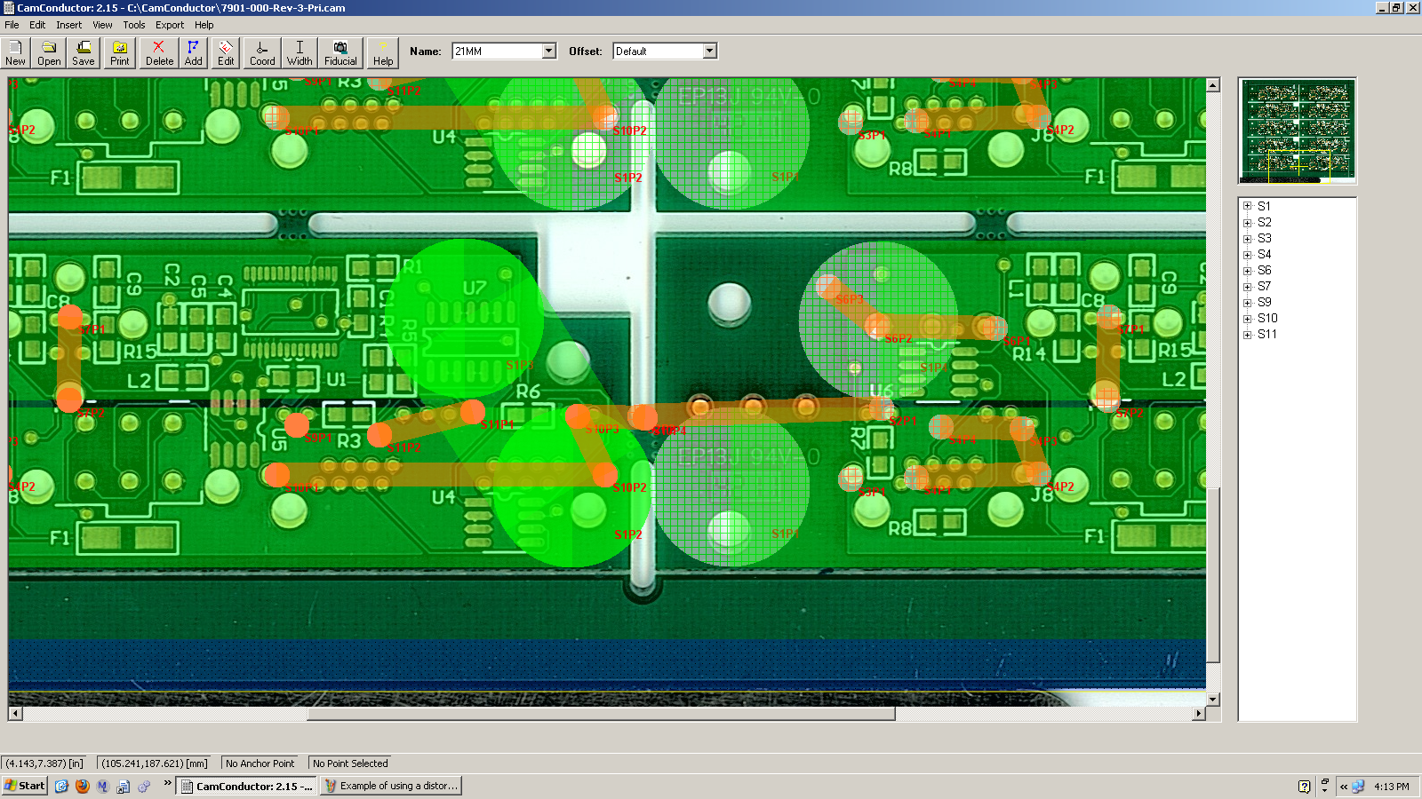
Selective Soldering Tips: Negative Z to Adjust For Board Warp
This is just one article in a series of articles discussing tips and tricks for using a selective soldering machine. Here at Worthington Assembly Inc. we have a selective soldering machine manufactured by RPS Automation. Our particular model is a 2010 Rhythm model. These article are written by the same person who's used this machine every day for years. From time to time, we come cross assemblies that are quite large (16" x 16") and quite flexible. They may be a standard 0.062" board but they're loaded with a lot of large heavy parts. When you put a lot of heavy parts over a large area, it's a perfect recipe for board warpage.
We recently had a job with just these conditions. We have supports on our fixture to try to help with this phenomenon. They're aluminum bars that are self supporting on the fixture, with a spring loaded hook that tries to pull up a heavy board so that it remains flat and does not bow down. But even with these aluminum support bars, the board still wanted to bow down. The only solution was to adjust the height of the nozzle by changing the "Z-Height" in our program.

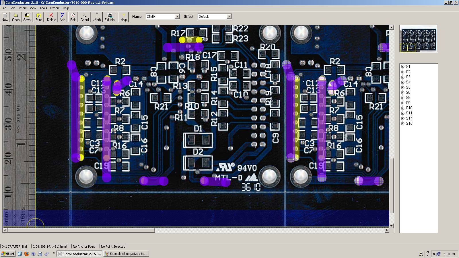
This can be tricky though because if you lower your z-height all the way across the whole assembly, the areas that are well supported by the edges of the fixture or the aluminum bars may have very poor hole fill or just plain not get soldered at all. So you will need to identify areas on your assembly where the board is going to warp so far down that there's a risk of the leads of the components coming into contact with your nozzle. As you can see in the image above, we start out with no offset on our z-height. But as our path gets closer and closer to the center of the board, where we experience the worst warpage, we decrease our z-height by as much as 1.25mm. This may not sound like much, but we often find even a quarter millimeter can make a huge difference in consistent hole fill.
It's been suggested that we reduce the z-height over the whole assembly and just increase the pump speed. The reasoning is "If you just increase the pump speed, the solder will flow high enough to fill the plated holes properly." This may be true in some circumstances, but you'll be making compromises. In most cases, when your pump speed is too high, you'll experience more bridging, increased dross build up, not to mention that your contact surface area may increase considerably, potentially causing contact with adjacent surface mount components. Yes ladies and gentlemen, selective soldering is a process that will challenge your creativity.
As always, if you have any questions, feel free to give me a call at (413) 624-6879 or send me an email at cdenney@worthingtonassembly.com.
Selective Soldering Tips: Start Where You Finish
This is just one article in a series of articles discussing tips and tricks for using a selective soldering machine. Here at Worthington Assembly Inc. we have a selective soldering machine manufactured by RPS Automation. Our particular model is a 2010 Rhythm model. These article are written by the same person who's used this machine every day for years. Sometimes a person can populate a board much quicker than a machine can solder the board. So if you find that you're piling up boards waiting for the machine to finish, there are a number of different things you can do to reduce the throughput time. I will address just one of the ways with this article.
When drawing a path for the machine to follow, it's important to begin your next path as close to where your previous path stopped. If the machine needs to travel a long distance, criss-crossing back and forth around the board, you'll dramatically increase your cycle time and decrease efficiency.
I know this sounds obvious, but by being diligent with this practice, we have decreased cycle times by as much as 50%. How does this happen? Well, when you first program your board, you may not have thought about every little detail. Once you've run a couple of boards for the first time, you notice issues such as missing a part or coming into contact with a surface mount part on the bottom. So you go into the program and add a couple new paths. But each time you do this, you're adding complexity, and if you're adding complexity without considering where your machine needs to travel, you'll ultimately end up wasting a lot of time with the nozzle traveling all around the board with no thought put into it.
As always, if you have any questions, feel free to give me a call at (413) 624-6879 or send me an email at cdenney@worthingtonassembly.com.
Request A Quote
Today, we're excited to announce that we have added a new page to our website that should make it easier for customers and potential new customers to request a quote from us. The URL is http://www.worthingtonassembly.com/request-a-quote/
We even have a customized shortened URL http://bit.ly/WAiRFQ
This page will describe all the details of the quoting process and what's required. This is most important for potential new customers, or customers who have not done business with a contract manufacturer before. For existing customers, they mostly know the drill already. You'll also find on that page a link to a Microsoft Word form that will help speed up the quoting process and answer almost any question we might have regarding your assembly. So check it out and let us know what you think.