
When Tim Cook announced the pricing for the Apple Watch Edition he didn't say $9,999. He said $10,000. Because when you get to this kind of price point, you specify your price in "thousands of dollars" not just "dollars".
Such is the world of capital equipment. Equipment pricing is measured in "tens-of-thousands" of dollars. So when you evaluate equipment like this, you don't take it lightly. But for this one, I can't help but gush...
Concept
The My600 is an absolutely breathtaking piece of engineering. The people who designed this thing (in Sweden) deserve to have their names written in the engineering hall of fame (if such an institution exists). I didn't fully appreciate this until I watched this machine in action. Just look at this thing run.
This is the real speed of the machine. I absolutely swear it is not sped up. It is printing up to 600 dots every second. It does this on the fly. Meaning that it does not stop moving to deposit a dot. It automatically calculate the trajectory of the dot based on the vertical speed of the dot and the horizontal speed of the head. Think of a plane dropping a bomb on a target. The plane needs to drop the bomb sometimes miles before it sees the target, depending on the speed and elevation of the plane.

The My600 uses the same physics as calculating when to drop a bomb
This is how it goes so fast. It doesn't need to stop movement in order to deposit solder. Think of how many calculations this thing needs to make every second in order to actually land this dot exactly where it belongs, with incredible accuracy. Here's a picture of a 0.5mm pitch QFN.

0.5mm Pitch QFN
I took this picture through one optic of a microscope. Look at the video again. This entire component is probably less than 200 dots so the My600 can print this entire footprint in a fraction of a second.
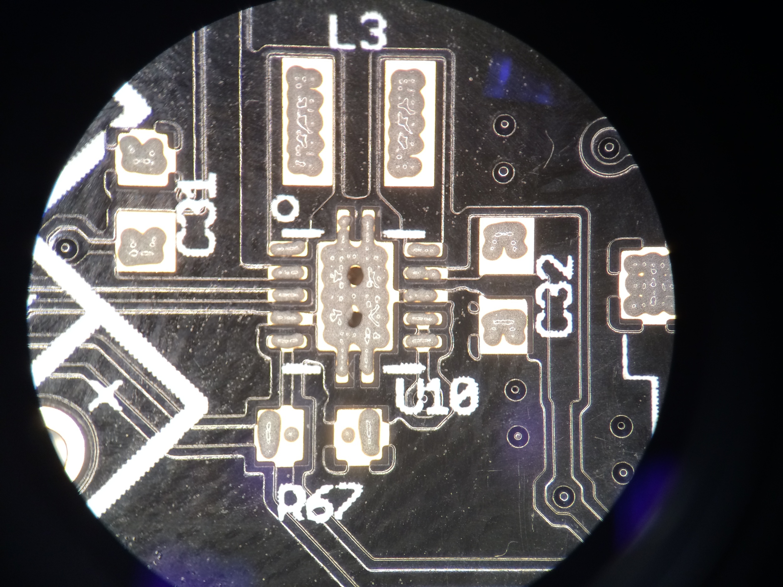
Home plating is possible too. Looks at R67
You can see how the individual dots create a line for the individual leads of the QFN. There are three dots that make up each line. The accuracy here is so impressive considering the speed of this machine. You can add more paste to that center ground pad. If you look closely you can see that there's a via in the center of the pad that would pull solder paste down into it. If the via pulled too much solder paste, you could just add extra. You can't do anything like this with a stencil. The stencil is just one thickness so you have to hope the engineer designed things with that in mind and didn't make the via too large.
Hardware
It all starts with a 4,000 lb granite composite frame. That's right. This whole machine is made from a rock. Not steel.

4,000 pound granite composite frame. Anywhere you see gray or black paint, that is granite
The machine needs this ultra heavy, rigid frame for stability. At Mycronic they have this machine sitting on a poured concrete floor. While the machine was running, you could feel the vibration in your feet. I can only imagine what this machine would do to a steel frame.
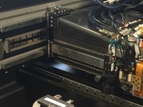
To the granite frame they add this cantilevered beam. It just floats in the air, affixed to only one side of the machine. Unlike 99% of all circuit board production equipment in this world that use a gantry mounted head (affixed to two sides of the machine), Mycronic chose to mount their head on this ultra light weight carbon fiber cantilevered support beam.

Ultra light carbon fiber cantilever beam. Notice it's affixed to only one side.
I'm told that this carbon fiber beam is the second most expensive item on the whole machine. Only the granite frame is more expansive. And it shows. Just think of how straight this thing needs to be. Any sort of flex or bow would completely throw off the accuracy of the machine. Imagine if you have the dispense head at the far end of the beam and you whip the head in the Y direction at 3G's. What do you think that would do to the beam? It would want to bow like a golf club. And yet it doesn't. The My600 maintains a 33 micron (a micron is a millionth of a meter) accuracy at 1.33 Cpk.

Copper power cables
Notice those huge copper cables on the side and floating above the beam? This is how power gets transferred to the dispense head and its various controls. Most machines would just use a simple ribbon cable to transfer power. But with this machine, because the head is experiencing up to 3G's of force, a typical ribbon cable simply would not hold up. So Mycronic designed these special cables to transfer power to the head while withstanding these ridiculous forces. Take a look at the video again and notice how much that cable is bouncing. That's deliberate. If it was too rigid, it could fail early. Designing it to be flexible gives it greater longevity.
Linear motors drive this beast. See those rounded rectangular blocks? Those are the magnets that are used to help propel the beam. You'll also notice smaller rounded rectangular blocks on the beam itself. Those are the magnets used to help propel the head. They work on the same principal as some roller coasters you may have been on before.
Linear motors
In order to cool all of this, the previous generation machine (the My500) used an offline chiller with a hose plumbed into the machine to keep the head cool. But the engineers at Mycronic came up with a way simpler solution. It's called a "vortex tube". Compressed air goes in, hot air escapes through an exhaust on one end, and cold air is directed to its destination out the other end. Absolutely amazing.
Finally, there's the actual dispense head, which gets mounted to this carbon fiber beam and is driven by the linear motors.

Dispense head holding a tube of solder paste.
This I'm told was the most complicated engineering challenge the team faced. It seems simple, but as with most things that seem simple I'm sure it's incredibly complicated. Basically, pneumatic pressure pushes a plunger down, keeping the pump full of solder. The pump then controls a very precise amount of pressure to feed the piezo which actually releases the solder paste. The piezo is capable of 600Hz but averages out to about 300Hz. That's the buzzing sound you hear in the video.

Port where the actual solder paste is released.
To put the above image into perspective, that hole is about 0.33mm in diameter. By comparison, an 0201 capacitor is a 0.6mm x 0.3mm rectangle.

Opposite side of the port, showing the shaft of the pump.
Software
The ultimate goal for all of this is to be able to deposit solder very precisely, but only where you want it. How do you define where you want it? Software.

My600 programming software.
The programming of this machine is ridiculously easy and fast. You import one file, specify which locations are SMT, and then the software does the rest. I programmed one side of the BeagleBoy myself in less than 5 minutes, with almost no training whatsoever. It was so easy and simple, that that's really all I have to say about the user interfacing software. I'm sure Mycronic spent a ridiculous amount of time on the backend software that controls everything. But for the user, there's really not much they need to do.
Benefits
There are things you can do with a jet printer that simply are not possible with a stencil. One of the challenges of using stencils is that you can only deposit one volume of paste across the whole assembly (there are stepped stencils but I won't get into them here). Your paste is only as thick as the stencil you've used. So your QFN's and 0402's have just the right amount of solder paste, but your 1206's and large inductors are starved for solder paste. Not an issue with a jet printer.
For instance if you have a part that should have a greater volume of paste, you can program the machine to add extra paste at that location. And best of all, it will remember that type of part so that the next time it sees a part like that again, it will use the same profile as before.

Slide from the Mycronic brochure
One of the biggest issues we have here is mixing complicated USB or SD card connectors on the same board with a very fine pitch QFN. You have to optimize your stencil around the QFN otherwise you'll have terrible yields. So oftentimes with USB connectors we have to manually add a dot of paste using a dispenser that's held by hand. The volume of paste that gets applied by this method is extremely variable, not to mention very time consuming. With a jet printer you can tell the machine to just make the paste a little thicker in one location and your issues are gone.
Then there are things that a jet printer can do that is not just difficult with a stencil, it's simply impossible. Like a 3D cavity in the board.
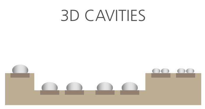
Try doing this with a stencil
Something like this would never have even been tried before jet printing. You'd have to add the paste by hand. A stencil could not simply reach in and apply paste here.
How about PoP (Package-on-Package or Part-on-Part) components. Today when we get an order for assemblies with PoP components, we need to create the PoP component ahead of time using a special carrier. But with a jet printer, you just place the part, run it through the printer again, and then build your whole assembly.

Package-on-package with virtually no stacking limit
Or how about when you build a board but then only realize afterward that you stencil was clogged and didn't get any paste on a few pads. Now you have all of the components already populated all around the board. You can't put it back in a stencil printer. Your only choice would be to add paste by hand. Not an issue with a jet printer.

Pre-mounted components are not an issue
Pin-in-paste has been a thing for many many years. But in order to do it right, you really needed to design your product to make it work. Typically, only OEM's could do this because the designer and the manufacturer were either the same person or at least working in the same office. But we don't have that luxury. So when we get surface mount components with thru-hole pins (like USB ports and HDMI connectors) we have to add the solder by hand after they've gone through the SMT process. You can cut apertures in your stencil for those pins but it's never quite enough solder paste. With a jet printer you can just keep adding more and more paste to that area until you find the correct ratio that results in a perfect solder joint.

High quality pin-in-paste is a reality
One of the other great challenges we have with our stencil printer today is that we can only run one job at a time. If we have a high volume job setup, we can't really slide in a single-piece order without wasting a lot of time. The stencil needs to be removed, the blades either need to be cleaned or swapped, the conveyor adjusted, support pins moved, etc. There's a lot involved in changing over a stencil printer. If you're exceptionally fast at it, you can probably do it in about 10 minutes if everything goes well. But with a jet printer, you simply load a different program, the conveyor adjusts automatically, and you print the other board. So not only can you fit that single-piece board into the process, but you can even be running two jobs at the same time and just switch back and forth between them seamlessly.
Which reminds me of another awesome feature. There's no need for support pins on this machine. The very first thing the machine does is map out the height of the PCB. If there is any bow or twisting of the PCB it's compensated for by this process. Take a look at the beginning of this video. You'll first see the board transferred into the machine on the conveyor, then a camera will locate the fiducials and then you will see a red laser shining on the board. This is the measurement process.
The machine does this mapping process the first time it runs a PCB. This is a thorough mapping process. Every PCB after this (of the same batch) it will perform a much shorter mapping process before printing. This helps keep the machine very precise, but also eliminate the need for support pins which are extremely important in a stencil printing process. When a squeegee blade presses down on the stencil, if the board underneath it is not well supported you will get a large gap and it will result in a terrible print. With this height mapping process it can compensate for a significant amount of warpage.
Speaking of warpage, a jet printer can also compensate for any shrink or stretch of a PCB, the same way a pick and place machine can compensate for shrink and stretch. When a machine locates a PCB it uses 3 fiducials. The 1st fiducial locates the board in the X and Y dimension. The 2nd fiducial tells the machine how much the PCB is rotated. The 3rd fiducial tells the machine how much the board is stretched or shrunk from the board house. With a stencil this is simply impossible. You just line up the PCB as close as you can and hope for the best. You're not going to stretch your stencil at all. This is normally not an issue, but if you were to run a very large board with very fine pitch components, it could become a real issue. A jet printer could simply compensate for this with math and be done with it.
You also save a ton of solder paste with this machine. A typical stencil printing operation, with a lot of changeover, results in well over 50% solder paste being wasted to the cleaning process. But with a jet printer, all the paste that's wasted is during purge and calibration. There is no cleaning process. No blades to wipe solder paste off of. No stencil to keep clean. Some My600 customers are reporting 98.5% utilization. Last year we spent $4545.80 on solder paste. And we likely through away over $2,000 worth of it. That's not nothing.
Decisions
There is no question that this technology is the way of the future. But remember the opening paragraph? All these benefits don't come cheap. Mycronic knows what they have here and they know it's great. Time to put my negotiator hat on.