So you've got a great idea and you want to bring it to market, but you don't know the first thing about hiring a manufacturer and working with them to get your product assembled? We are here to help. This is one piece in a series of articles that we'll be writing that will help people learn how to work with us to get their product assembled.
We see a lot of different, unique assemblies come through our shop. On average we are introducing a new job to our factory every single day. This means the assembly has never been built by us and likely has never been built by anybody. With this amount of new work, we've seen the good, the bad, and the downright ugly when it comes to footprints.
The most sinister of all footprints is the 0402 footprint. There's something about the 0402 component that just loves to drive us insane! The issue is that many footprints inadvertently cause the component to "tombstone" or worse "head-in-pillow". Here's what those defects look like.

This is what a "Head-In-Pillow" defect looks like. Notice how the right side isn't actually wetted to the component.

This is what a "Tombstone" defect looks like. It might be hard to notice at first, but the pad on the left has the 0402 capacitor standing straight up in the air.
The biggest culprit of all 0402 issues is the default 0402 footprint in the Eagle library that comes with every installation of Eagle (I love Eagle. I really do. I just hate this one footprint). So, if you have 0402 components in your design, please, for the love of all that is honest and good in this world, change that 0402 footprint to the one we recommend.
Here's a video showing me editing this footprint in Eagle.
The perfect 0402 Footprint
This video was made using the Eagle EDA tool. But here are the dimensions you'd want to use if you designed this in any other EDA tool.
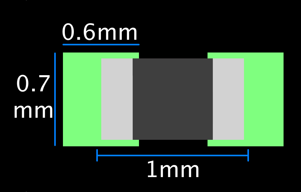
The Perfect 0402 Footprint
We have populated hundreds of thousands (probably millions) of 0402's with this footprint. We've had such success with this footprint that I had to reach out to the engineer who designed this footprint originally and thank him for his design. He thought I was ridiculous because it was just the standard dimensions that he found on a datasheet many years ago. But the difference is he actually created his from scratch, rather than relying on the default footprint in his EDA tool's library. And this is the key. Whenever you start using a new footprint, please check it against a datasheet and make sure it matches. Your manufacturer will thank you.
If you ever have any questions, please feel free to reach out to us. We'd love to hear from you. My email is address is cdenney@worthingtonassembly.com and our phone number is (413) 624-6879.