You’ll be malfunctioning within a day, you nearsighted scrap pile.

We do a lot of cool things here at Worthington Assembly. Some of them cooler than others. And as every typical American kid raised in the 80's, I've been a huge fan of Star Wars my whole life. So needless to say I was super excited when Paul Murphy of the R2 Builders Club reached out to us to build some assemblies for him.

Recently we had a chance to see Paul at Star Wars Night at a Boston Red Sox game. The reaction to his R2D2 unit was incredibly. More than a few kids ran up to give R2D2 a hug. I know I would have if I wasn't worried about Queen Amidala calling security on me.

It was exciting to see our work in real life. We assembled the Logic Display control boards for him. In his words "Logic Displays are the blinky lights in the rectangular openings of R2-D2's dome (2 front, 1 rear) that separate dead droids from the living". You can even see the "Assembled in Massachusetts" logo on the PCB.

Here's a video I shot showing Paul controlling his R2D2 unit from a distance before the Sox game.

You can learn more about his work by visiting is GitHub repository here

If we've built something for you and you would like us to blog about it, let us know. We love learning about what happens to the boards after they leave our factory.

How To Use CircuitHub

If you have ever wanted to try to use CircuitHub but weren't uncertain about the whole process, well there's good news. We've produced a short "how-to" video demonstrating CircuitHub. It will walk you through the whole process from importing your files, reconciling your part numbers, consigning material, choosing a board color, thickness, and copper weight, and finally hitting the buy button. We hope this will help new users get more familiar with the process and maybe existing users will learn something that they weren't aware of before.

Presentation At The Isenberg School Of Management

Over the past several months, WAi has been working with a smart group of MBA students from the Isenberg School of Management. It has been an enlightening and eye opening experience. We learned a lot and having them dig in and ask some tough questions got us to think about how we do things and helped us refine our process a bit. 

Their final presentation was today and we thought they did a great job so we wanted to share!

Working With A Manufacturer - The Best 0402 Footprint

So you've got a great idea and you want to bring it to market, but you don't know the first thing about hiring a manufacturer and working with them to get your product assembled? We are here to help. This is one piece in a series of articles that we'll be writing that will help people learn how to work with us to get their product assembled. 

We see a lot of different, unique assemblies come through our shop. On average we are introducing a new job to our factory every single day. This means the assembly has never been built by us and likely has never been built by anybody. With this amount of new work, we've seen the good, the bad, and the downright ugly when it comes to footprints.

The most sinister of all footprints is the 0402 footprint. There's something about the 0402 component that just loves to drive us insane! The issue is that many footprints inadvertently cause the component to "tombstone" or worse "head-in-pillow". Here's what those defects look like.

This is what a "Head-In-Pillow" defect looks like. Notice how the right side isn't actually wetted to the component.

This is what a "Head-In-Pillow" defect looks like. Notice how the right side isn't actually wetted to the component.

This is what a "Tombstone" defect looks like. It might be hard to notice at first, but the pad on the left has the 0402 capacitor standing straight up in the air.

This is what a "Tombstone" defect looks like. It might be hard to notice at first, but the pad on the left has the 0402 capacitor standing straight up in the air.

The biggest culprit of all 0402 issues is the default 0402 footprint in the Eagle library that comes with every installation of Eagle (I love Eagle. I really do. I just hate this one footprint). So, if you have 0402 components in your design, please, for the love of all that is honest and good in this world, change that 0402 footprint to the one we recommend. 

Here's a video showing me editing this footprint in Eagle.

The perfect 0402 Footprint

This video was made using the Eagle EDA tool. But here are the dimensions you'd want to use if you designed this in any other EDA tool.

The Perfect 0402 Footprint

The Perfect 0402 Footprint

We have populated hundreds of thousands (probably millions) of 0402's with this footprint. We've had such success with this footprint that I had to reach out to the engineer who designed this footprint originally and thank him for his design. He thought I was ridiculous because it was just the standard dimensions that he found on a datasheet many years ago. But the difference is he actually created his from scratch, rather than relying on the default footprint in his EDA tool's library. And this is the key. Whenever you start using a new footprint, please check it against a datasheet and make sure it matches. Your manufacturer will thank you.

If you ever have any questions, please feel free to reach out to us. We'd love to hear from you. My email is address is cdenney@worthingtonassembly.com and our phone number is (413) 624-6879.

Working With A Manufacturer - What Are Fiducials and Why Are They Useful?

So you've got a great idea and you want to bring it to market, but you don't know the first thing about hiring a manufacturer and working with them to get your product assembled? We are here to help. This is one piece in a series of articles that we'll be writing that will help people learn how to work with us to get their product assembled. 

We get this question all of the time. Many designers have no idea why they would put some random piece of copper on their board when it serves them absolutely no purpose.

Fiducials are reference points on the PCB for automated equipment. Its full name is "Fiducial Marker" and according to Wikipedia a Fiducial Marker is 

an object placed in the field of view of an imaging system which appears in the image produced, for use as a point of reference or a measure.

In other words, fiducials help machines recognize where an object is in its space. For PCB assembly this means that our stencil printing machine, pick and place machine, and AOI machine can recognize where the PCB is when it goes to perform its task.

We encourage customers to use 3 fiducials. If you can't fit 3 fiducials then 2 fiducials will generally suffice. But 3 fiducials is the best. Each one serves a purpose.

1st - The first fiducials helps the machine recognize where the PCB is in its space in the X and Y dimensions.

2nd - The second fiducial helps the machine recognize what orientation the PCB is in and also how skewed the PCB is in the clamps. If the PCB is rotated even 1/10th of a degree this could completely ruin the assembly if it weren't for fiducials. The machine is able to measure the angle that the board is rotated in the machine down to the nearest 1/100th of a degree and compensate all of the placements accordingly.

3rd - Finally, the third fiducials helps the machine compensate for any shrink or stretch of the PCB. Yes, believe it or not PCB's do vary by very small amounts over a long enough distance. This is very important for larger PCB's because they experience a much greater amount of stretch and/or shrink. This is especially true for double-sided SMT assemblies. After the first side is reflowed in the oven the board may have stretched, shrunk, bowed, flexed, whatever you want to call it. Having the third fiducials can help compensate for this effect.

The next question people ask is, well why stop at 3? Why not have a 4th? Well, imagine this scenario. Your PCB is placed inside the machine rotated 180 degrees. What happens when the machine goes to inspect the 3 fiducials? It will find your 4th fiducial and start populating the entire PCB thinking that it understands it orientation correctly. This has happened to us, more than once, by well meaning designers. So, for the sake of sanity and my ever growing collection of gray hairs, please only put 3 fiducials on the PCB.

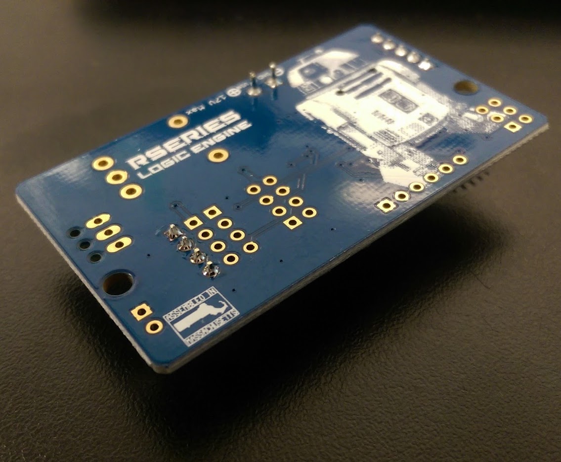
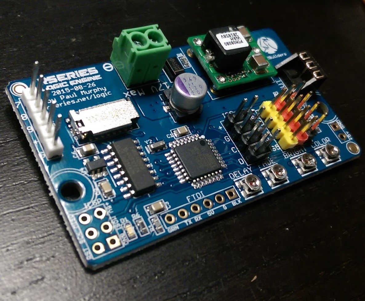
Fiducials are necessary whenever SMT components are going to be placed onto a circuit board. This includes double-sided SMT assemblies. So make sure to put fiducials on both sides of the PCB because cameras can't see through circuit boards. It needs those fiducials on both sides.

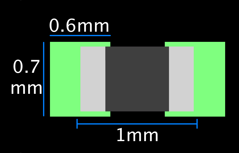
So when you are designing your next PCB or revising and existing PCB, please consider adding fiducials to your design. Many designers have found that using a 1mm round fiducial with a 2mm masking area around it works best. This masking area eliminates any glare that might reflect into the camera from the glossy finish of the masking. The best placement of these fiducials would be at the corners of your PCB. Not all the way up to the edge. This could cause the clamps of the machines to cover the fiducials. Try keeping them about 5mm from the edge or so. You can probably squeeze them in as tightly as 3mm but that's cutting it close. 5mm leaves plenty of breathing room.

We have put together a nice document about automated PCB handling. You can download it by clicking here. Also check out our best practices page if you haven't already done so for other helpful information.

As always, if you have any questions, please do not hesitate to reach out to us. We'd love to hear from you. You can email me at cdenney@worthingtonassembly.com or give us a call at (413) 397-8260.

Working With A Manufacturer - What's a BOM?

So you've got a great idea and you want to bring it to market, but you don't know the first thing about hiring a manufacturer and working with them to get your product assembled? We are here to help. This is the first in a series of articles that we'll be writing that will help people learn how to work with us to get their product assembled. 

So, what's a BOM? Well, you probably already know what a BOM is (Bill of Materials) but what are we specifically looking for from a BOM.  

There are 3 vital pieces of information.   

1. Reference Designator - this will be the location of your component. Something like R1 for resistors or U1 for IC's.  You begin with a prefix and then assign them a unique number. Here are the common prefixes

  • Capactiors "C"
  • Connectors "J"
  • Diodes "D"
  • Displays "DISP"
  • Ferrite Beads "FB"
  • IC's "U"
  • Inductors "L"
  • LED's "LED"
  • Modules "U"
  • Oscillators (Crystals) "Y" or "X"
  • Resistors "R"
  • Resistor Networks "RN"
  • Switches "SW"
  • Test Points "TP"
  • Transformers "T"
  • Transistors "Q"

2. Manufacturer's Part Number - we'll need to know what part to put in the location you've specified. And what we are looking for is a specific manufacture's part number. Saying "100k ohm resistor" isn't quite enough information. Think for a second how many pieces of information need to be specified for just a resistor. Value, tolerance, size, wattage, composition, temperature coefficienct, and operating temperature. And that's just for resistors! It's just too much information than we'd like to decide for you.  But an excellent resource is the Common Parts Library which WAi helped assemble in partnership with Octopart. We regularly keep these parts in stock and find them to be readily available and inexpensive compared to their alternatives.

3. Quantity - this is helpful for purchasing purposes. If you used a 1K resistor in 90 different locations, we'd rather not count those locations one by one to determine how many of that part number to buy. The quantity column will also help us double check our work. If we program our equipment and it tells us that there are 89 locations and you have a quantity of 90 specified, that will send up a red flag that there might be an issue.  

There's plenty more information that some of our customers put in their BOM that are useful but inessential. 

4. Line Items - this is handy for communicating back and forth. If we mention "There's a typo on line item 16" you'll know exactly where to look at your BOM for the issue.  

5. Descriptions - Descriptions are really helpful. Internally, we use Digikey's descriptions as much as possible because it's formatted nicely and has all of the pertinent information. We can also use the description to make sure that your manufacturer's part number is correct. If your description says that it should be a 4.7k resistor and when we look up the manufacturer's part number and find that it's a 47k resistor, we can check with you to make sure you've chosen the correct part number. You'd be surprised how many mistakes we catch with this technique. 

6. Datasheets - it's pretty useful to have a hyperlink to datasheets for components. Sometimes manufacturer's don't publicly release their datasheets (I'm looking at you Broadcom!) So if you provide us a link to datasheets it helps us speed up the process of programming your board. But don't stress about it. It's not necessary.  

7. Hardware Details - providing a nice full description of a piece of off the shelf hardware is great. If you give us a part number from McMaster-Carr for a hex nut, that's great. But a good full description of the nut is even more valuable. Is it stainless steel, or galvanized? Is it 3/16", how many turns per inch, etc. When we have a nice full description we can confidently buy these parts from an alternative manufacturer. I love McMaster-Carr (seriously. I love McMaster-Carr) but they're expensive. And we can find hardware for far less money from other suppliers. 

When you're done, here's what a BOM will more or less look like. They're generally formatted in a table that can be parsed by Excel or another spreadsheet program. CSV files and tab separated files work great too. We'd honestly prefer them over a proprietary format like Excel or OpenOffice.

Example of a BOM (Bill Of Materials)

Example of a BOM (Bill Of Materials)

BOM's are vital. Will live and die by our customer's BOM. If you have any questions we'd love to hear from you. You can email me at cdenney@worthingtonassembly.com or give us a call at (413) 397-8260.  

A Visit To Mycronic To Learn About The My600 Jet Printer

When Tim Cook announced the pricing for the Apple Watch Edition he didn't say $9,999. He said $10,000. Because when you get to this kind of price point, you specify your price in "thousands of dollars" not just "dollars". 

Such is the world of capital equipment. Equipment pricing is measured in "tens-of-thousands"  of dollars. So when you evaluate equipment like this, you don't take it lightly. But for this one, I can't help but gush...


Concept

The My600 is an absolutely breathtaking piece of engineering. The people who designed this thing (in Sweden) deserve to have their names written in the engineering hall of fame (if such an institution exists). I didn't fully appreciate this until I watched this machine in action. Just look at this thing run.

This is the real speed of the machine. I absolutely swear it is not sped up. It is printing up to 600 dots every second. It does this on the fly. Meaning that it does not stop moving to deposit a dot. It automatically calculate the trajectory of the dot based on the vertical speed of the dot and the horizontal speed of the head. Think of a plane dropping a bomb on a target. The plane needs to drop the bomb sometimes miles before it sees the target, depending on the speed and elevation of the plane. 


The My600 uses the same physics as calculating when to drop a bomb

The My600 uses the same physics as calculating when to drop a bomb

This is how it goes so fast. It doesn't need to stop movement in order to deposit solder. Think of how many calculations this thing needs to make every second in order to actually land this dot exactly where it belongs, with incredible accuracy. Here's a picture of a 0.5mm pitch QFN.  

0.5mm Pitch QFN

0.5mm Pitch QFN

I took this picture through one optic of a microscope. Look at the video again. This entire component is probably less than 200 dots so the My600 can print this entire footprint in a fraction of a second.  

Home plating is possible too. Looks at R67

Home plating is possible too. Looks at R67

You can see how the individual dots create a line for the individual leads of the QFN. There are three dots that make up each line. The accuracy here is so impressive considering the speed of this machine. You can add more paste to that center ground pad. If you look closely you can see that there's a via in the center of the pad that would pull solder paste down into it. If the via pulled too much solder paste, you could just add extra. You can't do anything like this with a stencil. The stencil is just one thickness so you have to hope the engineer designed things with that in mind and didn't make the via too large.


Hardware

It all starts with a 4,000 lb granite composite frame. That's right. This whole machine is made from a rock. Not steel.  

4,000 pound granite composite frame. Anywhere you see gray or black paint, that is granite

4,000 pound granite composite frame. Anywhere you see gray or black paint, that is granite

The machine needs this ultra heavy, rigid frame for stability. At Mycronic they have this machine sitting on a poured concrete floor. While the machine was running, you could feel the vibration in your feet. I can only imagine what this machine would do to a steel frame.  

To the granite frame they add this cantilevered beam. It just floats in the air, affixed to only one side of the machine. Unlike 99% of all circuit board production equipment in this world that use a gantry mounted head (affixed to two sides of the machine), Mycronic chose to mount their head on this ultra light weight carbon fiber cantilevered support beam. 

Ultra light carbon fiber cantilever beam. Notice it's affixed to only one side.

Ultra light carbon fiber cantilever beam. Notice it's affixed to only one side.

I'm told that this carbon fiber beam is the second most expensive item on the whole machine. Only the granite frame is more expansive. And it shows. Just think of how straight this thing needs to be. Any sort of flex or bow would completely throw off the accuracy of the machine. Imagine if you have the dispense head at the far end of the beam and you whip the head in the Y direction at 3G's. What do you think that would do to the beam? It would want to bow like a golf club. And yet it doesn't. The My600 maintains a 33 micron (a micron is a millionth of a meter) accuracy at 1.33 Cpk

Copper power cables

Copper power cables

Notice those huge copper cables on the side and floating above the beam? This is how power gets transferred to the dispense head and its various controls. Most machines would just use a simple ribbon cable to transfer power. But with this machine, because the head is experiencing up to 3G's of force, a typical ribbon cable simply would not hold up. So Mycronic designed these special cables to transfer power to the head while withstanding these ridiculous forces. Take a look at the video again and notice how much that cable is bouncing. That's deliberate. If it was too rigid, it could fail early. Designing it to be flexible gives it greater longevity. 

Linear motors drive this beast. See those rounded rectangular blocks? Those are the magnets that are used to help propel the beam. You'll also notice smaller rounded rectangular blocks on the beam itself. Those are the magnets used to help propel the head. They work on the same principal as some roller coasters you may have been on before. 

Linear motors

Linear motors

In order to cool all of this, the previous generation machine (the My500) used an offline chiller with a hose plumbed into the machine to keep the head cool. But the engineers at Mycronic came up with a way simpler solution. It's called a "vortex tube". Compressed air goes in, hot air escapes through an exhaust on one end, and cold air is directed to its destination out the other end. Absolutely amazing.

Finally, there's the actual dispense head, which gets mounted to this carbon fiber beam and is driven by the linear motors.

Dispense head holding a tube of solder paste.  

Dispense head holding a tube of solder paste.  

This I'm told was the most complicated engineering challenge the team faced. It seems simple, but as with most things that seem simple I'm sure it's incredibly complicated. Basically, pneumatic pressure pushes a plunger down, keeping the pump full of solder. The pump then controls a very precise amount of pressure to feed the piezo which actually releases the solder paste. The piezo is capable of 600Hz but averages out to about 300Hz. That's the buzzing sound you hear in the video.  

Port where the actual solder paste is released.  

Port where the actual solder paste is released.  

To put the above image into perspective, that hole is about 0.33mm in diameter.  By comparison, an 0201 capacitor is a 0.6mm x 0.3mm rectangle. 

Opposite side of the port, showing the shaft of the pump.  

Opposite side of the port, showing the shaft of the pump.  


Software

The ultimate goal for all of this is to be able to deposit solder very precisely, but only where you want it. How do you define where you want it? Software.

My600 programming software.  

My600 programming software.  

The programming of this machine is ridiculously easy and fast. You import one file, specify which locations are SMT, and then the software does the rest. I programmed one side of the BeagleBoy myself in less than 5 minutes, with almost no training whatsoever.  It was so easy and simple, that that's really all I have to say about the user interfacing software. I'm sure Mycronic spent a ridiculous amount of time on the backend software that controls everything. But for the user, there's really not much they need to do.


Benefits

There are things you can do with a jet printer that simply are not possible with a stencil. One of the challenges of using stencils is that you can only deposit one volume of paste across the whole assembly (there are stepped stencils but I won't get into them here). Your paste is only as thick as the stencil you've used. So your QFN's and 0402's have just the right amount of solder paste, but your 1206's and large inductors are starved for solder paste. Not an issue with a jet printer.

 For instance if you have a part that should have a greater volume of paste, you can program the machine to add extra paste at that location. And best of all, it will remember that type of part so that the next time it sees a part like that again, it will use the same profile as before. 

Slide from the Mycronic brochure

Slide from the Mycronic brochure

One of the biggest issues we have here is mixing complicated USB or SD card connectors on the same board with a very fine pitch QFN. You have to optimize your stencil around the QFN otherwise you'll have terrible yields. So oftentimes with USB connectors we have to manually add a dot of paste using a dispenser that's held by hand. The volume of paste that gets applied by this method is extremely variable, not to mention very time consuming. With a jet printer you can tell the machine to just make the paste a little thicker in one location and your issues are gone.

Then there are things that a jet printer can do that is not just difficult with a stencil, it's simply impossible. Like a 3D cavity in the board.

Try doing this with a stencil

Try doing this with a stencil

Something like this would never have even been tried before jet printing. You'd have to add the paste by hand. A stencil could not simply reach in and apply paste here. 

How about PoP (Package-on-Package or Part-on-Part) components. Today when we get an order for assemblies with PoP components, we need to create the PoP component ahead of time using a special carrier. But with a jet printer, you just place the part, run it through the printer again, and then build your whole assembly.

Package-on-package with virtually no stacking limit

Package-on-package with virtually no stacking limit

Or how about when you build a board but then only realize afterward that you stencil was clogged and didn't get any paste on a few pads. Now you have all of the components already populated all around the board. You can't put it back in a stencil printer. Your only choice would be to add paste by hand. Not an issue with a jet printer.

Pre-mounted components are not an issue

Pre-mounted components are not an issue

Pin-in-paste has been a thing for many many years. But in order to do it right, you really needed to design your product to make it work. Typically, only OEM's could do this because the designer and the manufacturer were either the same person or at least working in the same office. But we don't have that luxury. So when we get surface mount components with thru-hole pins (like USB ports and HDMI connectors) we have to add the solder by hand after they've gone through the SMT process. You can cut apertures in your stencil for those pins but it's never quite enough solder paste. With a jet printer you can just keep adding more and more paste to that area until you find the correct ratio that results in a perfect solder joint.

High quality pin-in-paste is a reality

High quality pin-in-paste is a reality

One of the other great challenges we have with our stencil printer today is that we can only run one job at a time. If we have a high volume job setup, we can't really slide in a single-piece order without wasting a lot of time. The stencil needs to be removed, the blades either need to be cleaned or swapped, the conveyor adjusted, support pins moved, etc. There's a lot involved in changing over a stencil printer. If you're exceptionally fast at it, you can probably do it in about 10 minutes if everything goes well. But with a jet printer, you simply load a different program, the conveyor adjusts automatically, and you print the other board. So not only can you fit that single-piece board into the process, but you can even be running two jobs at the same time and just switch back and forth between them seamlessly. 

Which reminds me of another awesome feature. There's no need for support pins on this machine. The very first thing the machine does is map out the height of the PCB. If there is any bow or twisting of the PCB it's compensated for by this process. Take a look at the beginning of this video. You'll first see the board transferred into the machine on the conveyor, then a camera will locate the fiducials and then you will see a red laser shining on the board. This is the measurement process.

The machine does this mapping process the first time it runs a PCB. This is a thorough mapping process. Every PCB after this (of the same batch) it will perform a much shorter mapping process before printing. This helps keep the machine very precise, but also eliminate the need for support pins which are extremely important in a stencil printing process. When a squeegee blade presses down on the stencil, if the board underneath it is not well supported you will get a large gap and it will result in a terrible print. With this height mapping process it can compensate for a significant amount of warpage. 

Speaking of warpage, a jet printer can also compensate for any shrink or stretch of a PCB, the same way a pick and place machine can compensate for shrink and stretch. When a machine locates a PCB it uses 3 fiducials. The 1st fiducial locates the board in the X and Y dimension. The 2nd fiducial tells the machine how much the PCB is rotated. The 3rd fiducial tells the machine how much the board is stretched or shrunk from the board house. With a stencil this is simply impossible. You just line up the PCB as close as you can and hope for the best. You're not going to stretch your stencil at all. This is normally not an issue, but if you were to run a very large board with very fine pitch components, it could become a real issue. A jet printer could simply compensate for this with math and be done with it.

You also save a ton of solder paste with this machine. A typical stencil printing operation, with a lot of changeover, results in well over 50% solder paste being wasted to the cleaning process. But with a jet printer, all the paste that's wasted is during purge and calibration. There is no cleaning process. No blades to wipe solder paste off of. No stencil to keep clean. Some My600 customers are reporting 98.5% utilization. Last year we spent $4545.80 on solder paste. And we likely through away over $2,000 worth of it. That's not nothing.


Decisions

There is no question that this technology is the way of the future. But remember the opening paragraph? All these benefits don't come cheap. Mycronic knows what they have here and they know it's great. Time to put my negotiator hat on.

We Have A New Website

It had recently come to our attention that our website was a bit... long in the tooth. So we spent some time over the holiday break to update our website.

The short story is, we have a fresh new look and the layout is much simpler and should load much faster.

The long story is that we were formerly hosted on HostGator and used Wordpress as our content management system. This worked ok, and was SUPER cheap, but there's so much management with Wordpress. We would get so much spam that we had to turn off our commenting system. Plus, in order to get things to render properly in all browsers we had to constantly edit the code that displays the page. The worst part is that whenever we had to perform an update to the theme (which was quite often) we'd have to re-edit the code every time. Eventually, we just got tired of dealing with it and let it languish. And something as important as a website should not be neglected. 

I've been hearing ads for Squarespace for years. They even had a commercial for the 2014 Super Bowl. I had avoided trying it because I didn't want to learn something new. But after playing with it for just 30 minutes, I felt like an expert. The software is really impressive and the mobile app for putting together blog posts is really slick. So we decided to switch over to Squarespace for hosting our website and we're pleased with the results. If you haven't checked it out head on over to www.worthingtonassembly.com and take a look.

For those of you who subscribed to the blog via email, nothing should change except the delivery system of the email. You'll be getting the emails from MailChimp now and the format should look a little different. For those of you that subscribed via RSS, you will need to update your RSS URL. I'm just not technically astute enough to know how to automatically do this. And if you're reading this, you're presumably interested enough to want to resubscribe manually. The new URL is http://www.worthingtonassembly.com/blog/?format=rss

Thank you all for reading this blog and if you ever have any questions, please don't hesitate to get in touch.

Octopart's Common Parts Library

Today Octopart announced what I think is a really valuable tool. The Common Parts Library We worked with Sam and Janine over at Octopart and helped them identify popular, and more importantly, readily available parts to build a common parts library. This will be a library of components that are known to be well stocked at distributors and perhaps even your contract manufacturer (like us). What will make this library particularly valuable is when you're designing a new product and you just need to find a basic resistor, cap, LED, oscillator, or some other such part to perform a simple task, without diving into the complicated filter engines of large distributors.

Just browsing the library makes me want to design a new board. I hope you find it valuable and let us know if you think anything is missing.